User Manual
OrpheLink
Version 1.1.4
OrpheLink functionality includes several key features:
- Site-to-Site Connection: Establishes a secure connection between different sites.
- LAN-to-LAN Connection: Connects Local Area Networks across different locations.
- Exit Node: Allows you to designate an exit node to direct traffic through specific nodes.
All connections between Nodes utilize TLS 1.3 and QUIC protocols, ensuring a high level of security.
OrpheLink utilizes a Three-Layer Topology Architecture to give users full visibility and granular control over their network deployment,
stretching from a high-level site overview down to individual node connections.:
Layer 1 : Site Topology View
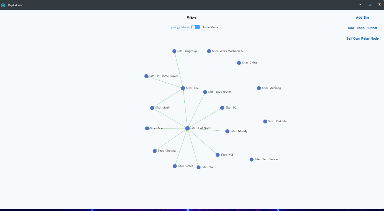
The Site Topology View provides a macro-level network overview where administrators can construct and audit a Site's blueprint.
Within this view, you can register nodes, determine boot behaviors, provision localized routing policies, define inter-node tunnel tracking,
and view discovered local networks.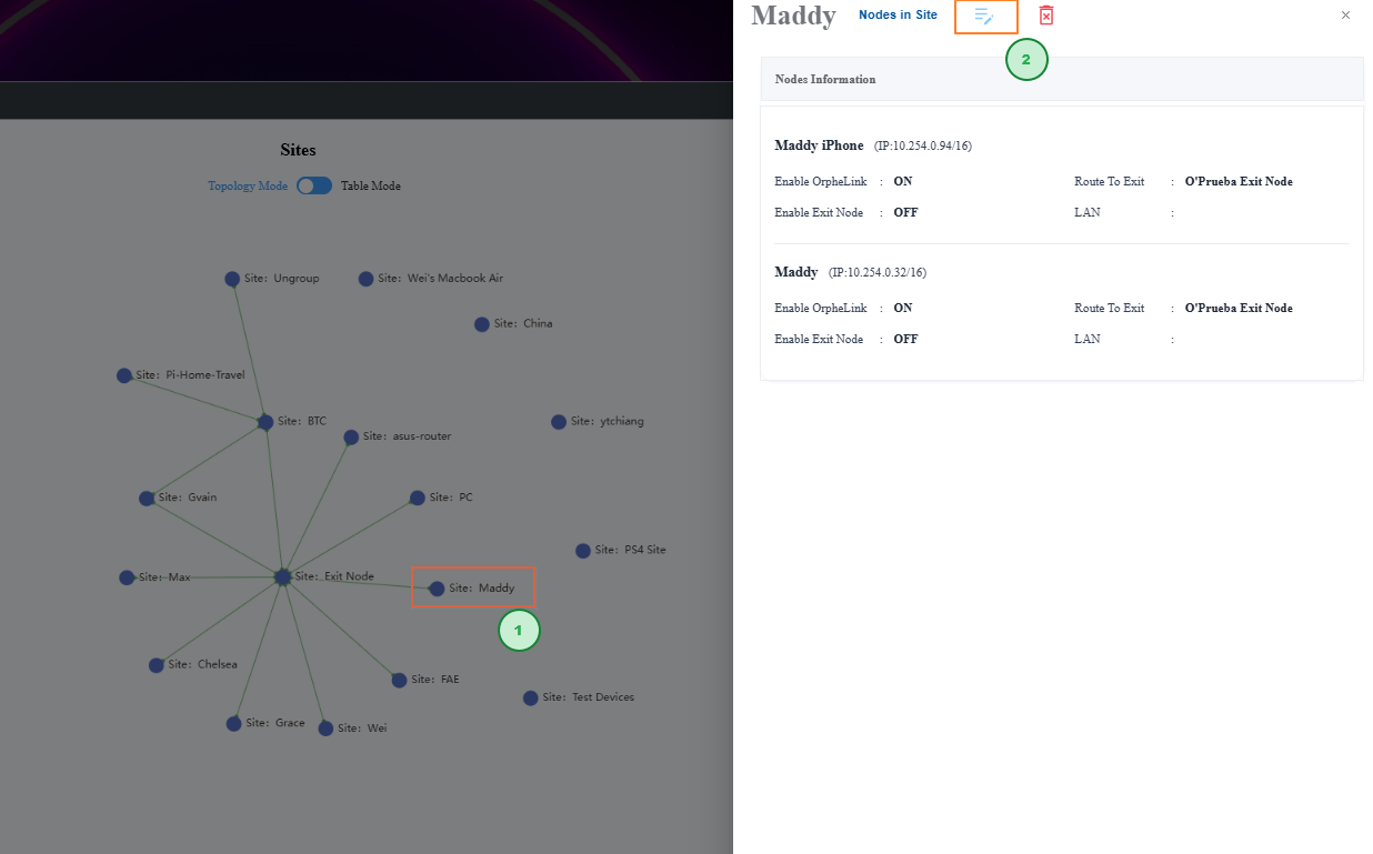
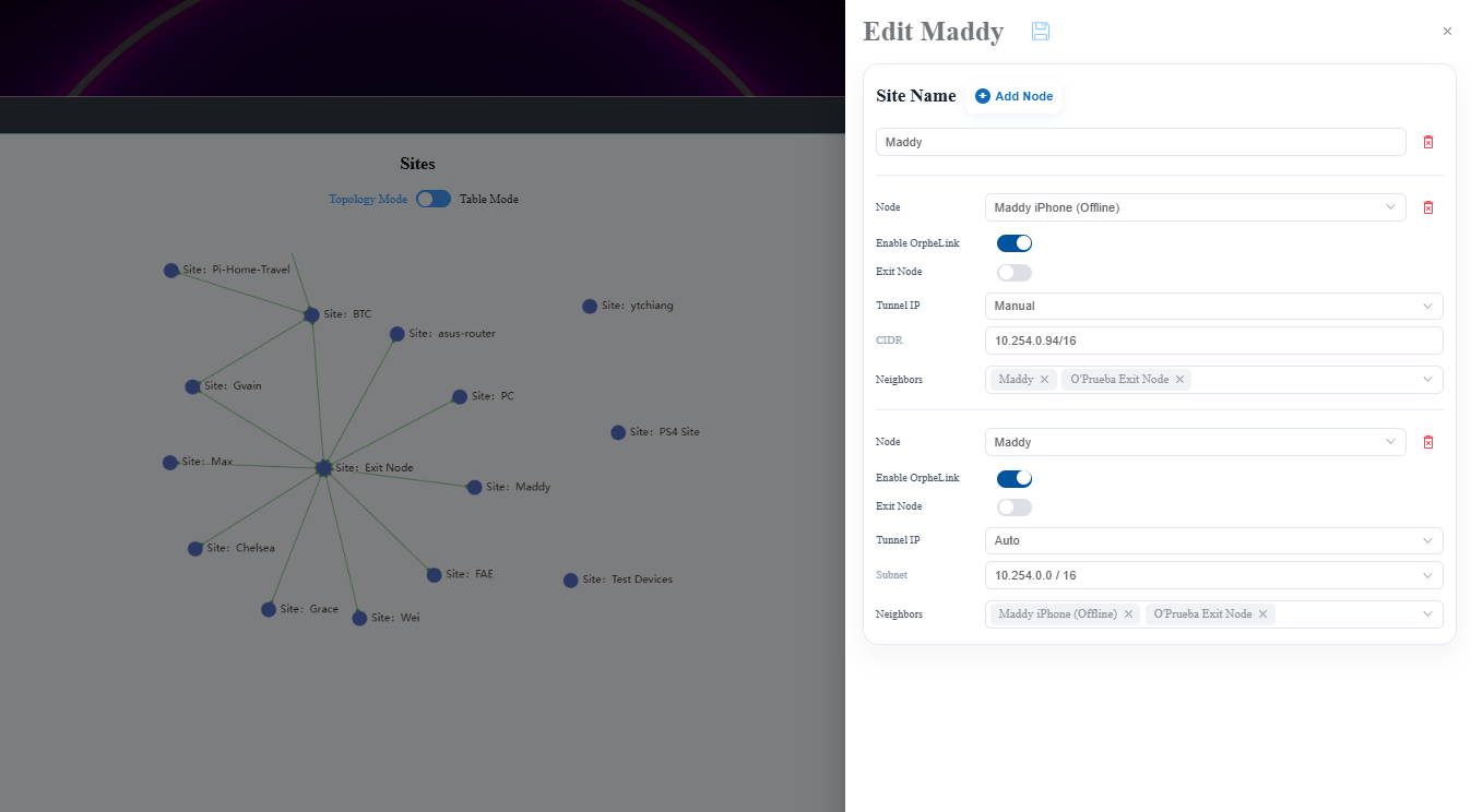
Clicking the Edit button opens the configuration modal to modify specific node behaviors, advanced routing policies, and network bypass rules.
| Name | Descriptions |
|---|---|
| Topology of Site | Display current sites connections |
| Add Tunnel Subnet | Create tunnel subnet range: If the node tunnel IP is set to Auto, it will be assigned from the tunnel subnet range by the OrpheLink to establish P2P connections. |
| Add Self Own Relay node | Establish your own relay node with a public IP and configurable transmission rate limits. |
| Add site | Create new site: Assign nodes, set exit node ,tunnel IP, define nodes neighbors connections, and add LAN. |
| Enable OrpheLink | Enable: Establishes the P2P connection automatically after rebooting the node. - Disable: Establishes the P2P connection manually after rebooting the node. |
| Exit node | Designate as the exit node that "route to exit" node traffic through this exit node before forwarding it. |
| SNAT (Only appears when Exit Node is ON) |
Controls source network address translation for the gateway. • Enable: Masks internal IPs behind the exit node for plug-and-play connectivity. • Disable: Preserves original device IPs to allow upstream firewalls to perform granular traffic auditing. |
| Tunnel Subnet / Tunnel IP | Defines the virtual IP range (CIDR) for internal P2P routing. • Auto: System auto-allocates range to prevent IP conflicts. • Manual: Manually customize the CIDR range. |
| Node Color |
|


 N
N C
C
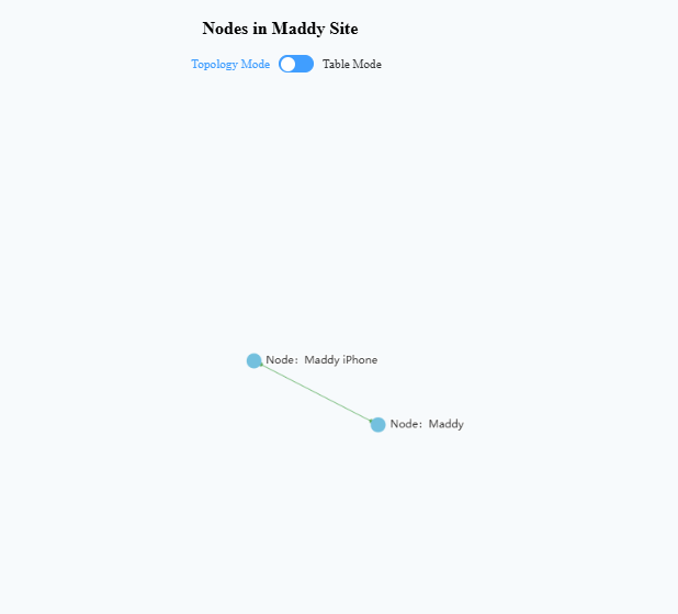
Layer 2: Nodes in Site View
Clicking "Nodes in Site" reveals all managed nodes mapped to that site. 
Hovering over or selecting a node pulls up a live status panel, and clicking the Edit button opens the configuration modal to modify specific node behaviors,
advanced routing policies, and network Environment rules.

| Name | Descriptions |
| Enable OrpheLink | Controls the Data Plane connectivity ON(Default): Activates the Data Plane and opens all secure P2P tunnel links. OFF: Temporarily disabling P2P communication. However, the Control Plane remains active, allowing the node to still be managed via the dashboard. |
| Authentication to Access | Zero-Trust Security: Intercepts cross-node access with a dynamic login page. Users must authenticate credentials before gaining access to this node. |
| Node discovery | Enable: Improves NAT traversal capability, but connections may be flagged as suspicious, potentially triggering firewall alerts. Disable: Connects to O'Prueba’s relay node or a customer's self-own relay node to achieve NAT traversal. |
| Relay Transport | Enable: When a direct connection fails, forwards traffic to another node via a relay node. Disable: Does not allow traffic forwarding via a relay node. |
| Enable On Boot | Auto-Recovery Switch (On Reboot): Determines the tunnel's automated behavior after a hardware reboot or power-up. ON (Default): The P2P connection automatically after rebooting the node.. OFF: Tunnels remain completely offline after booting. |
| Environment Rules | WAN Subnet Bypass Rule Split Tunneling: Bypasses OrpheLink tunnels to use existing paths. Example: Traffic from branch offices (172.16.1.x) to headquarters (10.10.1.x) will use the existing VPN directly instead of the OrpheLink Tunnel. |
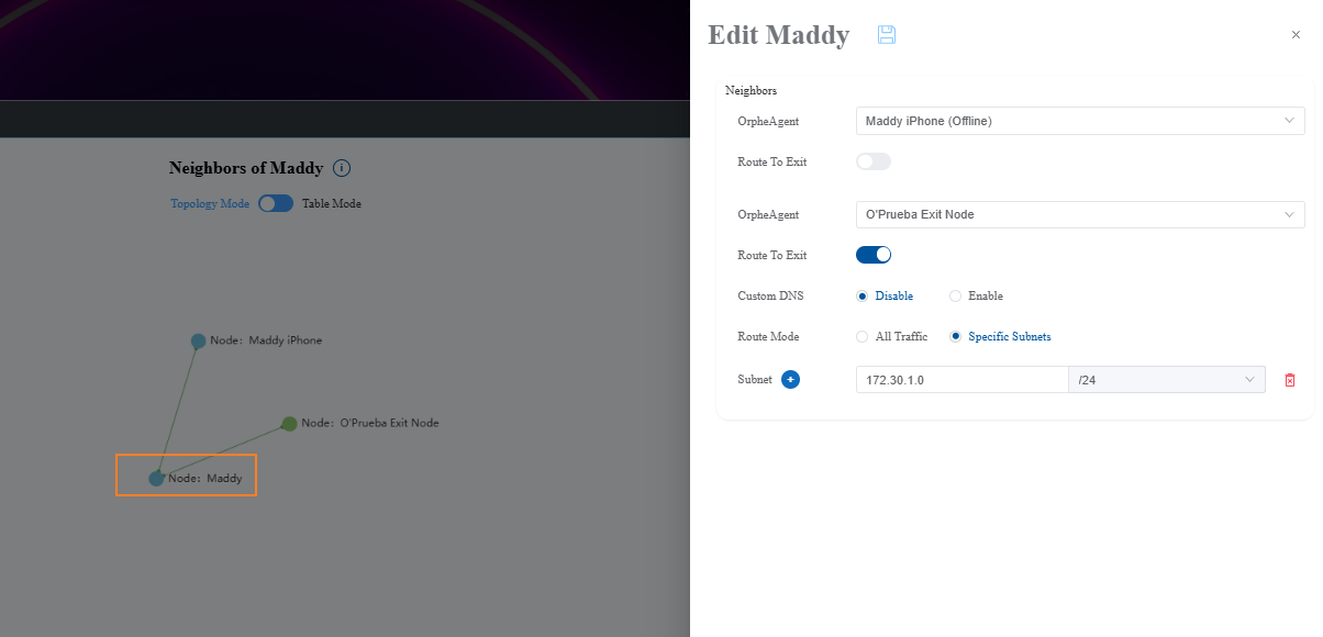
Layer 3: Neighbor of Node View
View a single node's connections. Use this page to setup Route-to-Exit, choose Route Mode, switch and set Custom DNS.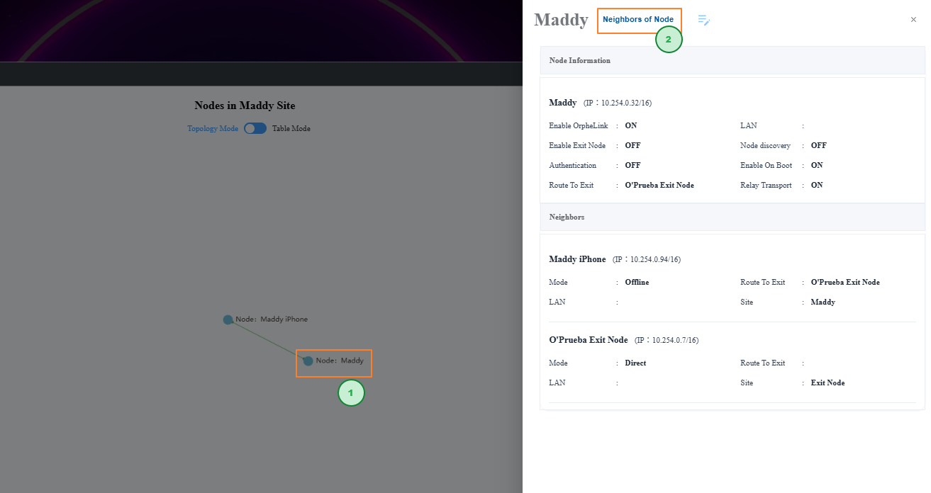
| Name | Descriptions |
| Neighbors | The nodes connection to select node. |
| Route to Exit | Select an Exit Node and turn this ON to route all device traffic through that specific gateway exit. |
| Route Mode | Determines how traffic is routed to the Exit Node: All Traffic: Routes all network data through the gateway. Specific Subnets: Routes only the customized subnet ranges you define to the Exit Node. |
| Custom DNS (Only available in All Traffic Mode) |
Enable: Transmits and applies custom DNS server settings to the node. These settings are cleared from devices upon link deletion. Disable: Suspends custom DNS propagation. |
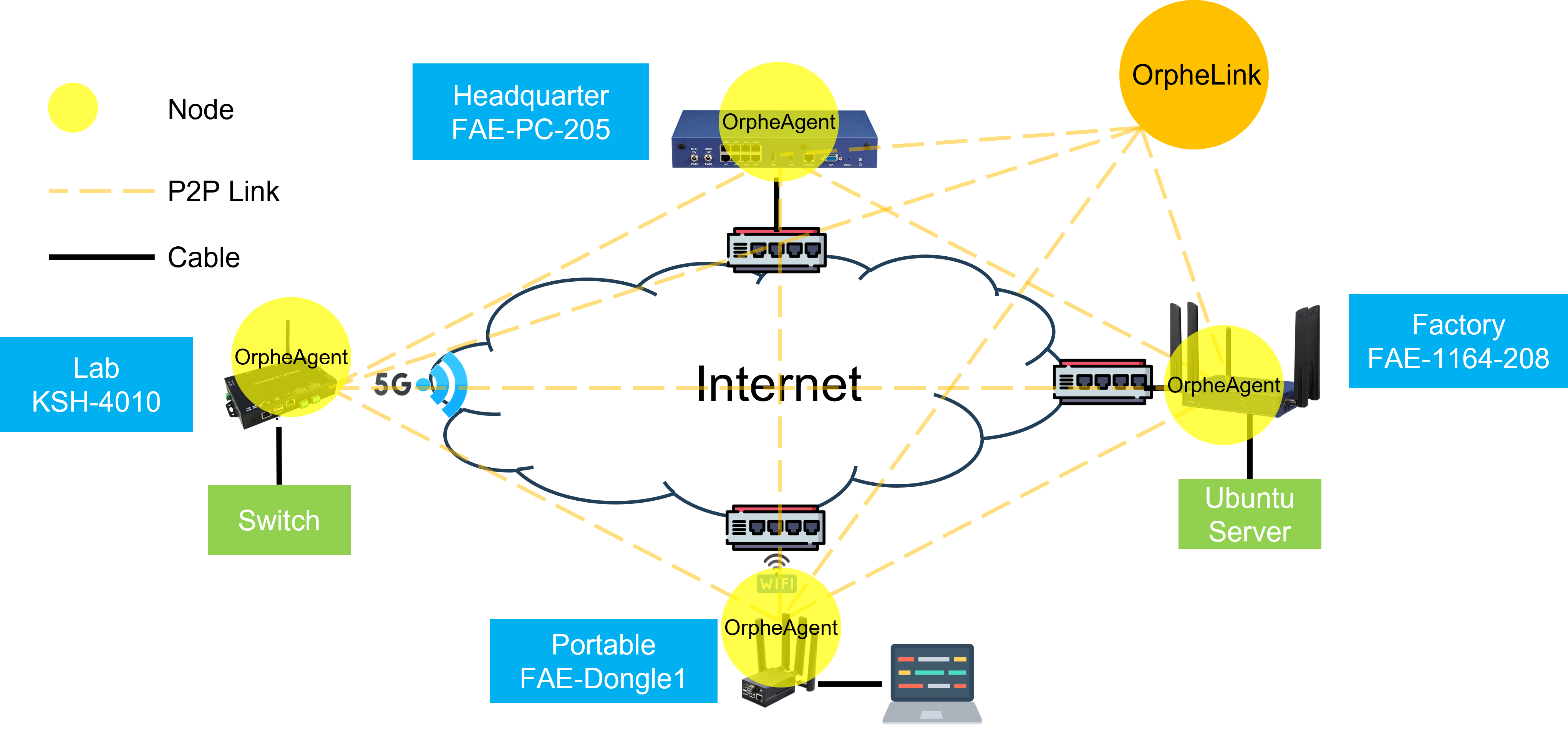
Setup Scenario:
Devices at different locations even in different countries have clients behind NAT with private IP addresses.
Using OrpheLink, these devices can communicate with each other through a secure tunnel, enabling direct data transfer even across NATs.
|
Location |
Name |
Agent Type |
WAN IP |
LAN |
Client |
|
HQ |
FAE-1164-208 |
Binary |
Cable 192.168.100.74 |
192.168.208.0/24 |
Ubuntu 24.04 Server 192.168.208.2 |
|
Lab |
KSH-4010 |
Container |
5G Network 10.139.28.25 |
192.168.1.0/24 |
EstiNet Switch 192.168.1.200 |
|
Factory |
FAE-PC-205 |
Container |
Cable 172.30.1.205 |
N/A |
N/A |
|
Portable |
FAE-Dongel1 |
Binary |
Wi-Fi 192.168.210.6 |
192.168.106.0/24 |
Laptop MSI |
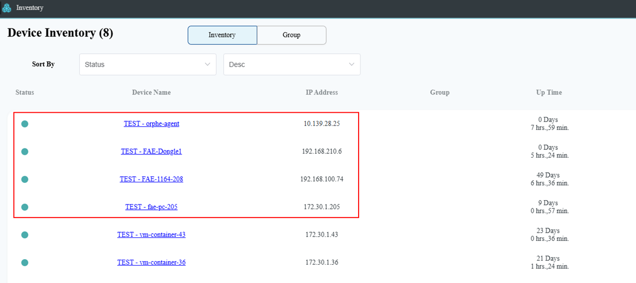
Login OrpheLink and navigate to inventory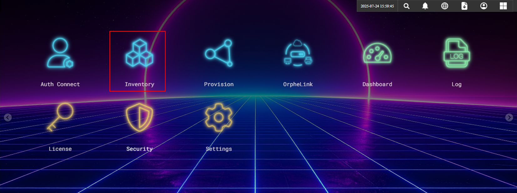
Check that OrpheAgent devices are listed in the inventory
Click OrpheLink icon to set Links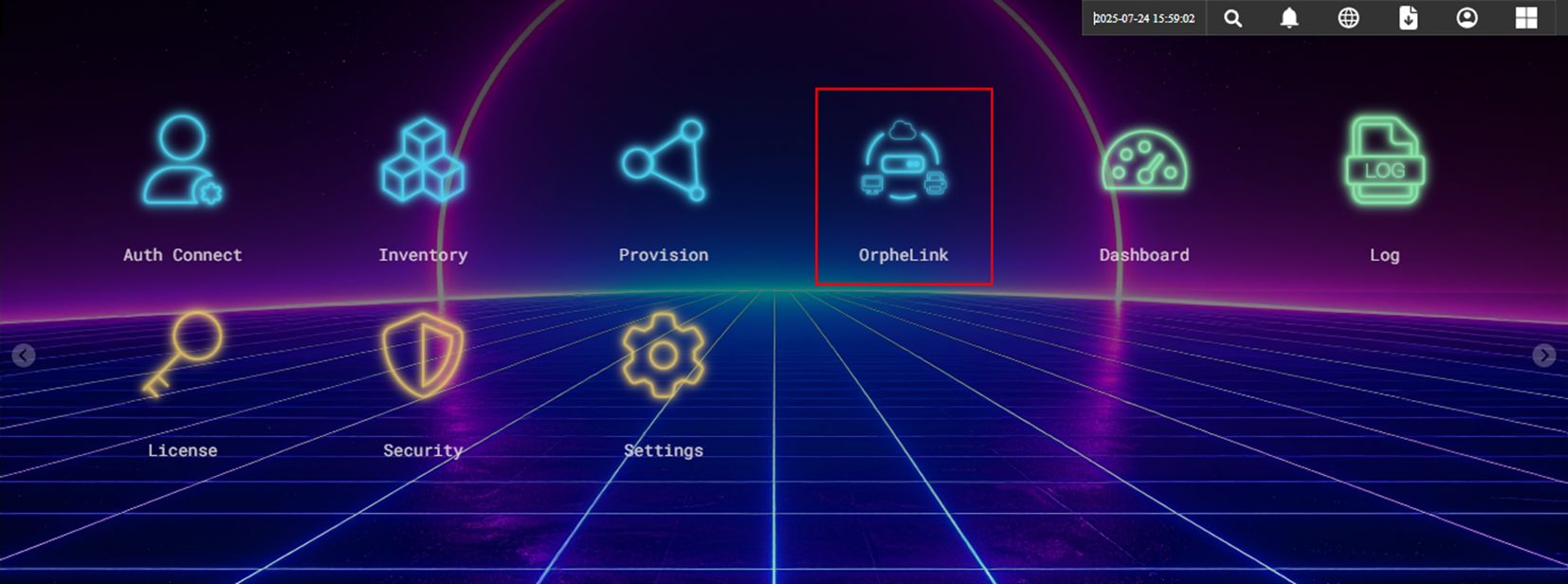
Any OrpheAgent devices not yet configured will be placed in the 'Ungroup' site by default.
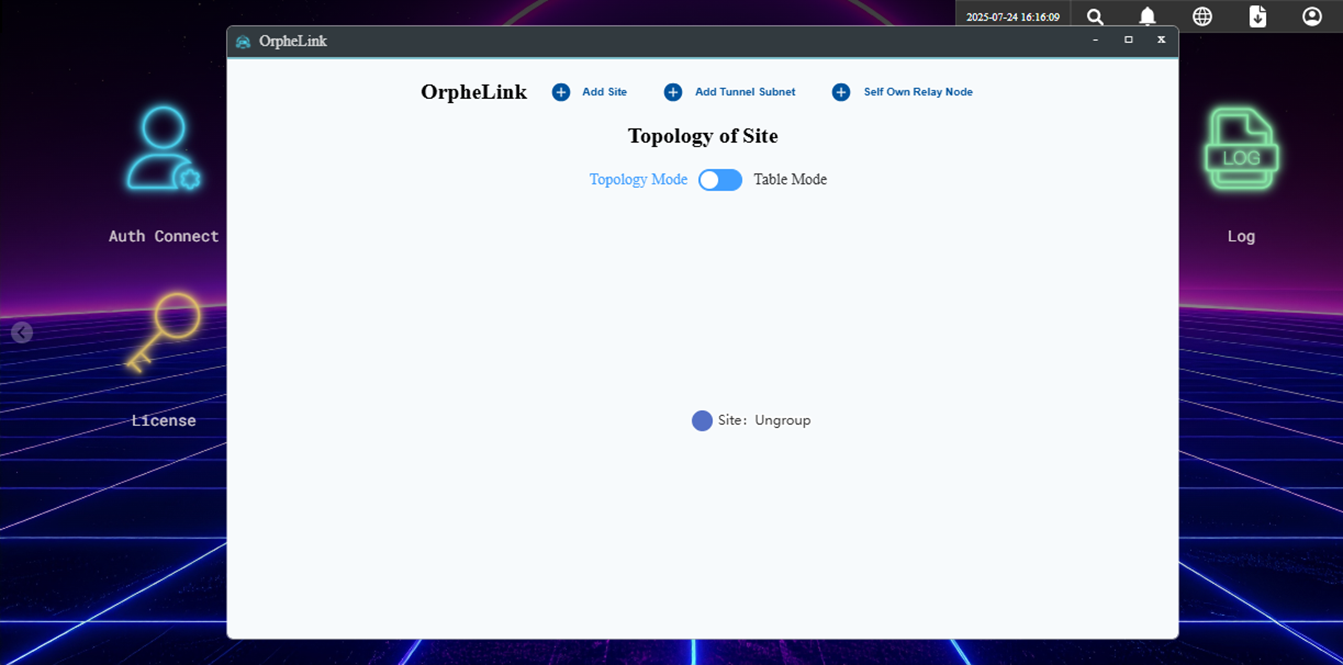
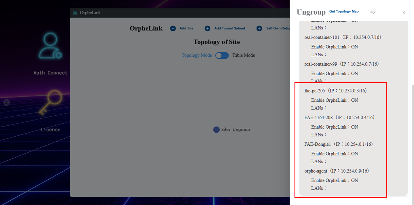
Click on the 'Ungroup' icon to see the number of OrpheAgent devices in the ungrouped site
Click to Add site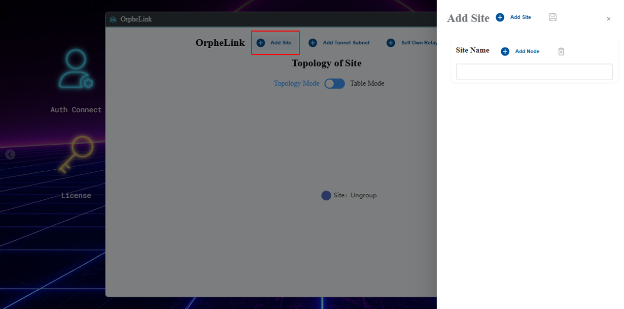
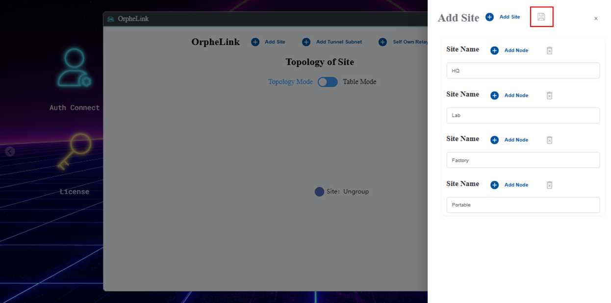
Add four sites named HQ, Lab, Factory, and Portable, then click 'Save'
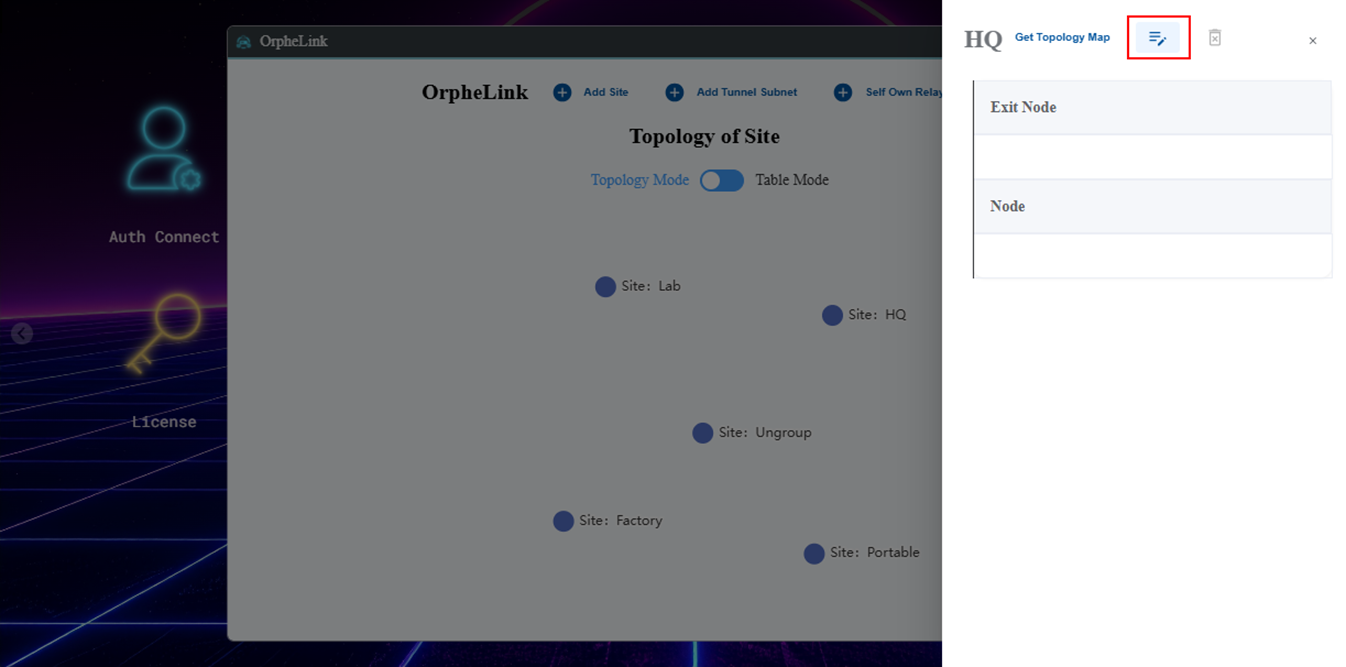
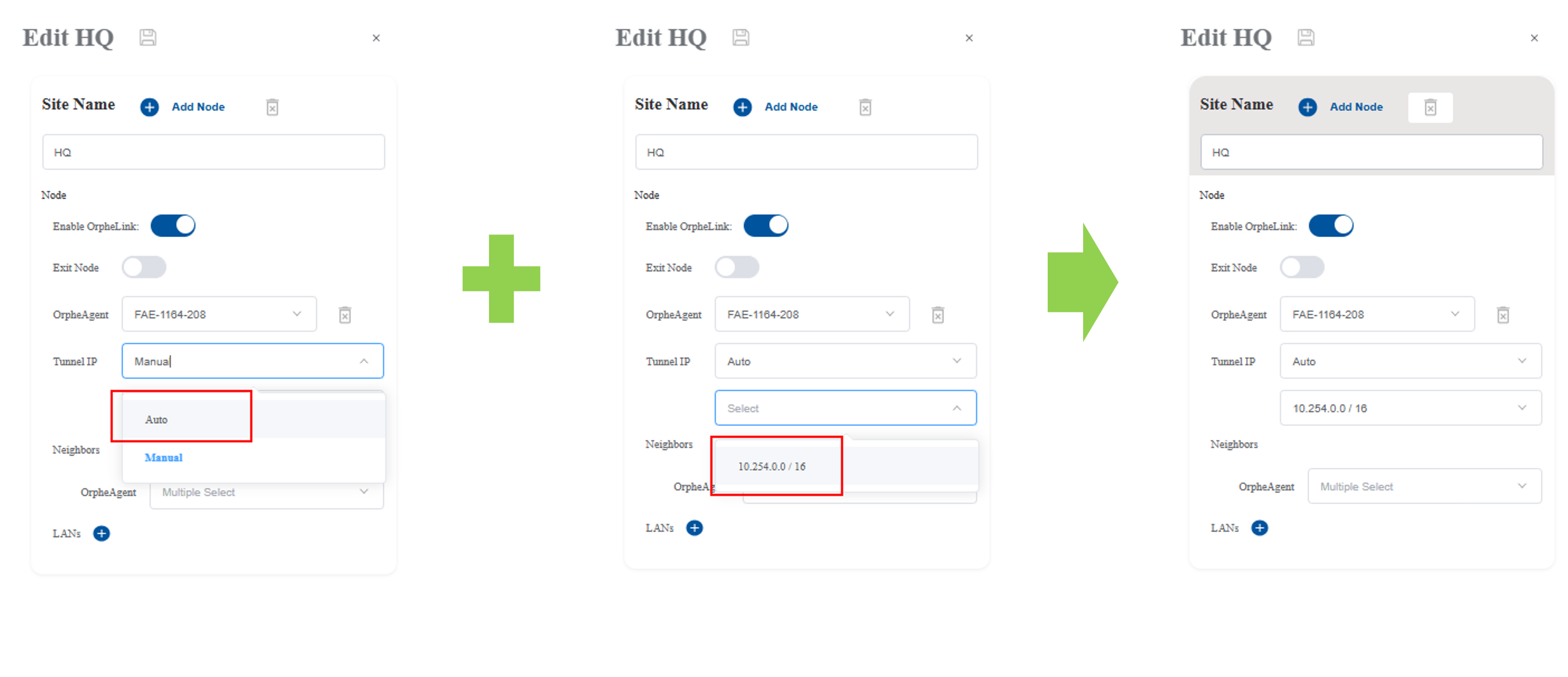
Click" Add Node" to Add OrpheAgent device and set the connections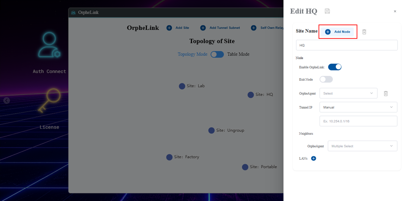
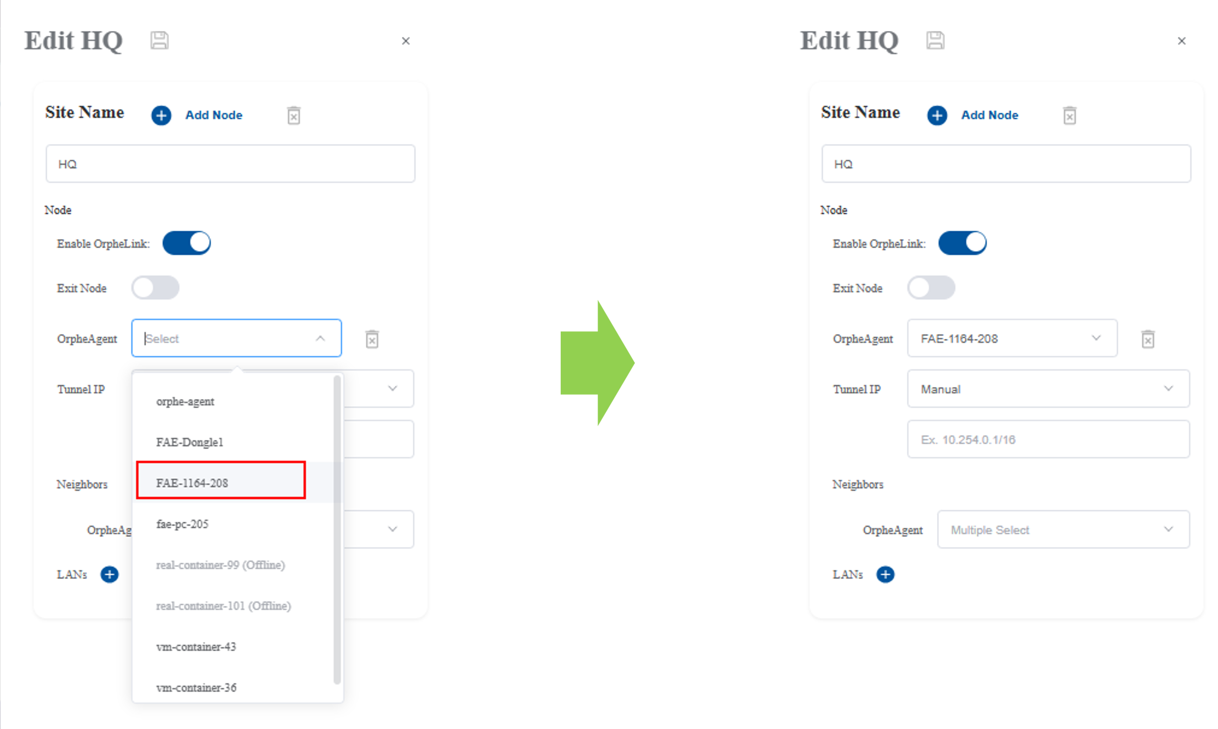
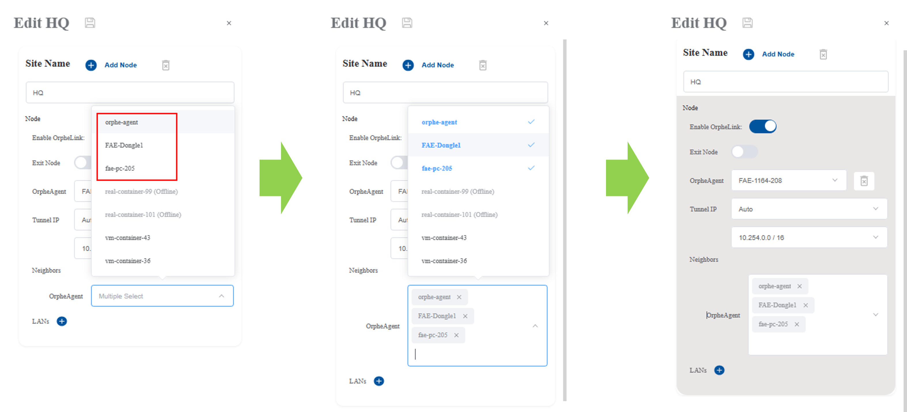
Add neighbors and select which OrpheAgent nodes to connect
Click 'Add LANs' and select from the dropdown list.
This configures a LAN-to-LAN connection, allowing endpoint devices to access remote OrpheAgent devices."
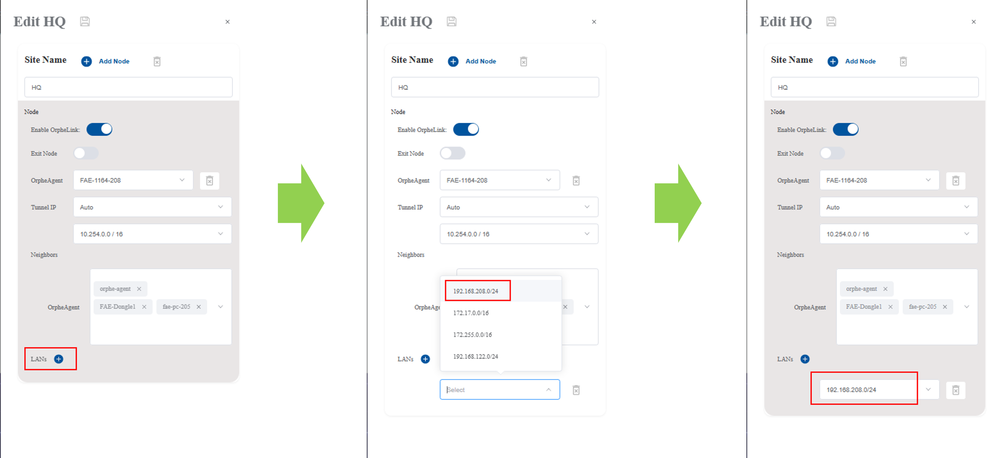
Click Save icon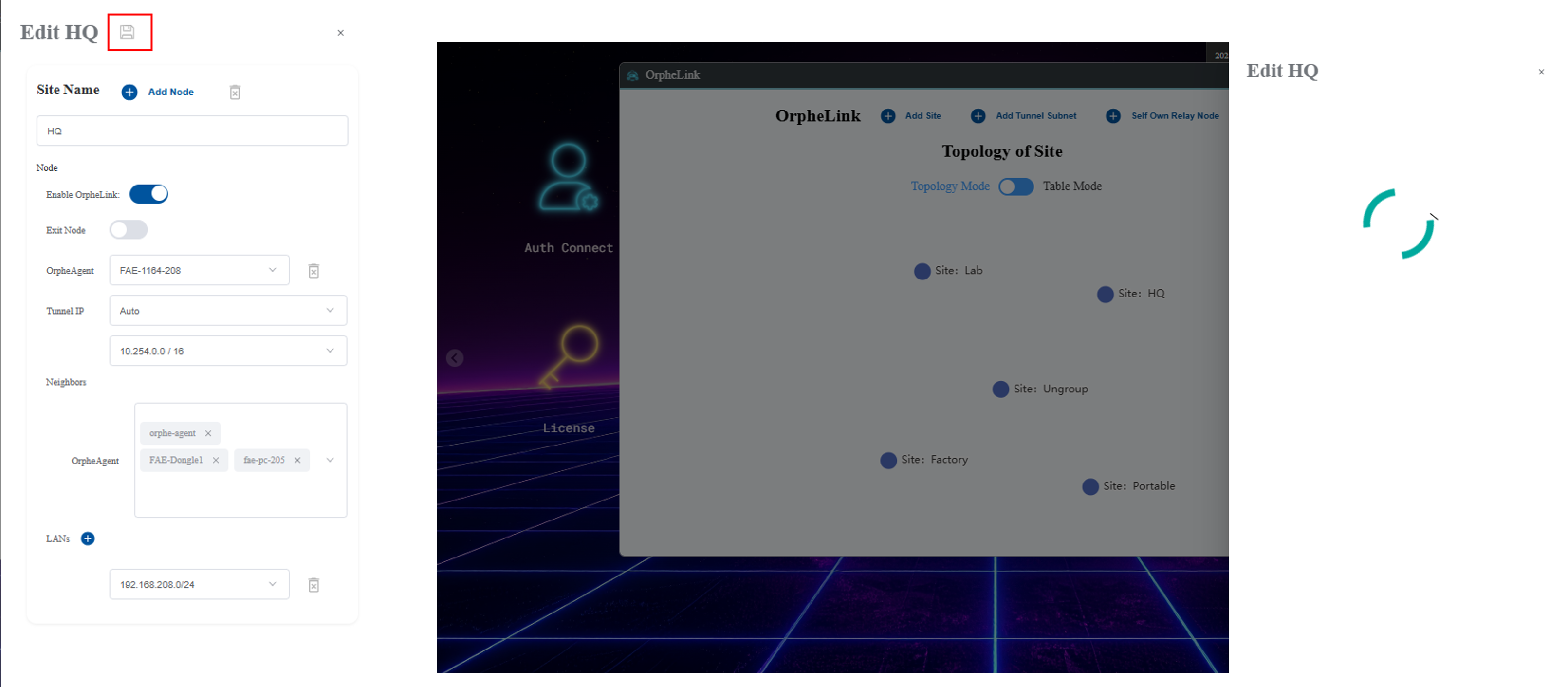
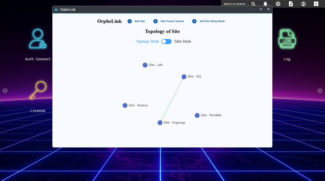
The connection between site HQ and the Ungroup site occurs because node FAE-1164-208 is assigned to site HQ, whereas its neighbors—FAE-Dongle1, KSH-4010, and FAE-PC-205—remain in the Ungroup site
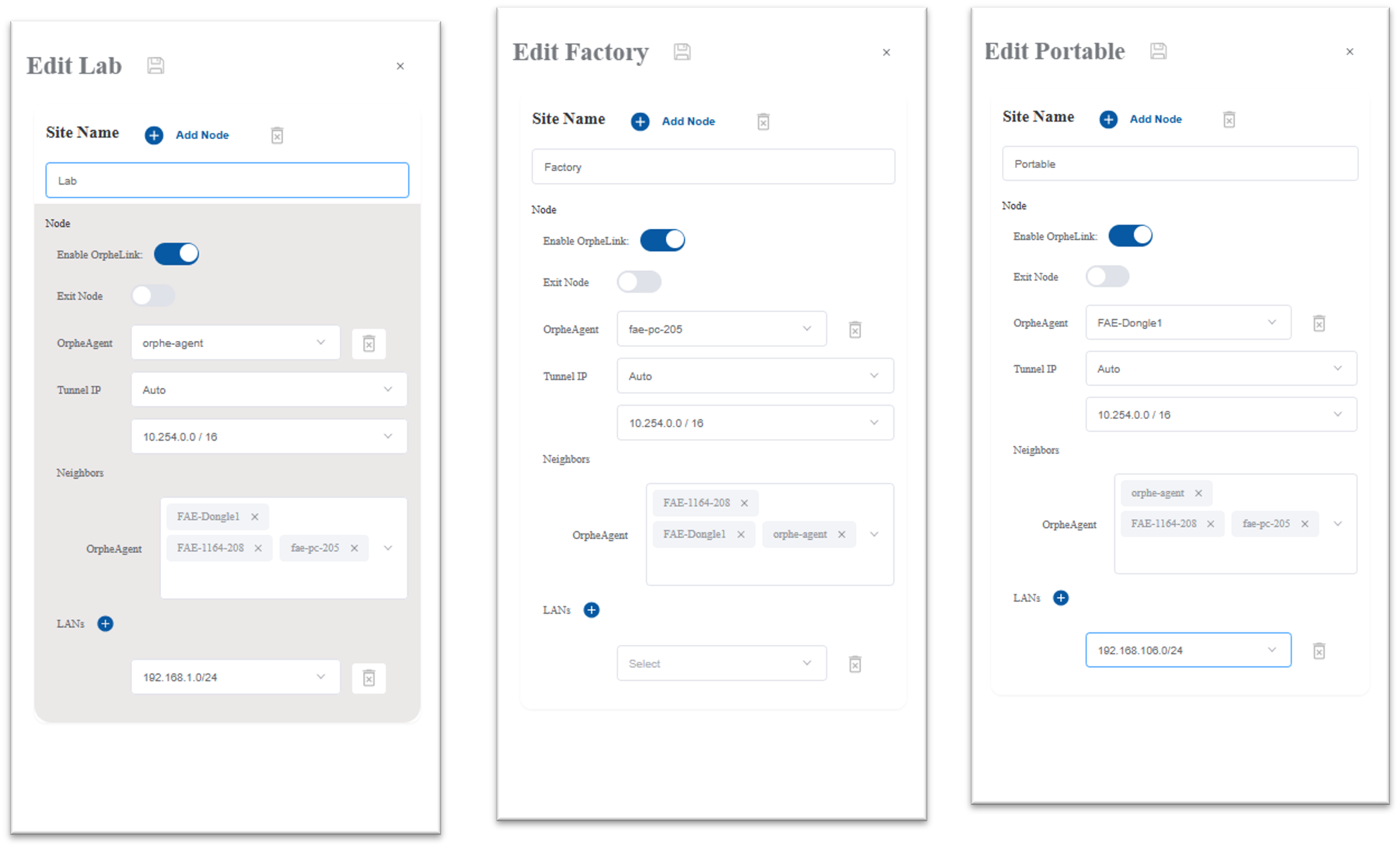
Next, configure the remaining sites and nodes following the same procedure:
-
Set up the Lab site and add node KSH-4010. Then, add the neighbor nodes and configure the LAN connections.
-
Set up the Factory site and add node FAE-PC-205. Add the neighbor nodes.
-
Set up the Portable site and add node FAE-Dongle1. Add the neighbor nodes and configure the LAN connections.
After completing the setup, the site topology is illustrated in the figure below.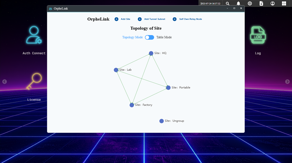
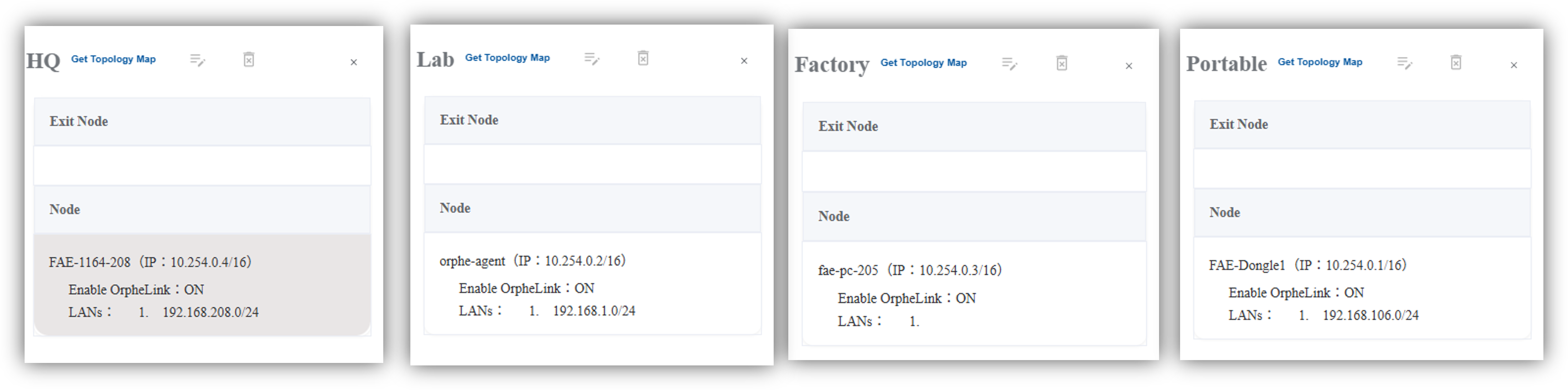
For each site, the Tunnel IP and LAN settings are listed in the table below, accompanied by screenshots of the configuration.
|
SIte |
Node |
Tunnel IP |
LANs |
|
HQ |
FAE-1164-208 |
10.254.0.4 |
192.168.208.0/24 |
|
Lab |
KSH-4010 |
10.254.0.2 |
192.168.1.0/24 |
|
Factory |
FAE-PC-205 |
10.254.0.3 |
N/A |
|
Portable |
FAE-Dongle1 |
10.254.0.1 |
192.168.106.0/24 |
After completing the setup, the devices are connected and ready for communication.


